
Trial Period: March 2026
Author: 夏水无痕
Acquired usage quota through the official WeChat account of Chargerlab.com. Below is the original project introduction:
“This trial ITXPower open-source project test board is equipped with the YX2265 main control chip, supports 5–42V wide voltage input, and can stably output 48V with a rated power of 600W. It supports DC5525, XT30, XT60, and Lenovo square port input, and is compatible with PC power supplies such as ATX, SFX, 1U, 2U; server power supply CRPS; laptop power supply DC5525 port, square port, etc.“
Appearance and Ports: 17*17cm, similar in size to a Mini-ITX motherboard.
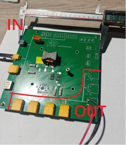
For interfaces, the left side supports DC5525, XT30, XT60, and Lenovo square port input, with the XT60 connector also supporting upward angle input. The 24-pin interfaces on the other sides are reserved for power supply. The top-right corner has XH 3-pin and 4-pin headers reserved for connecting a fan. The board I received has a chip labeled YX22105, which should be the 100V version of the YX2265 chip, supporting up to 100V input/output.
The bottom and right side are output ports, already with four XT60 male connectors installed, and three XT60 positions reserved.
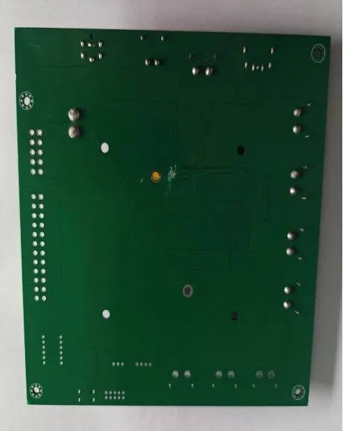
The back of the board has no components, only pins and solder joints. Laying it flat on a desk is a little uneven; it can be raised on all four corners with M3 standoffs, with a heat sink hole in the middle. The XT30 connector I bought is a bit tight, and plugging/unplugging presses down on the board. You can also use a standoff in the middle so the board won’t bend when plugging wires.
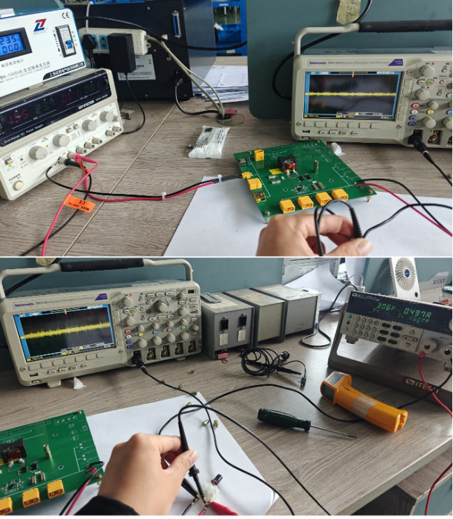
The DIY fast-charge board side hasn’t been done yet. In this trial, the setup used was 180W adjustable power supply → development board → 150W electronic load (no large resistor, my electronic load can max 150W, so higher power wasn’t tested).
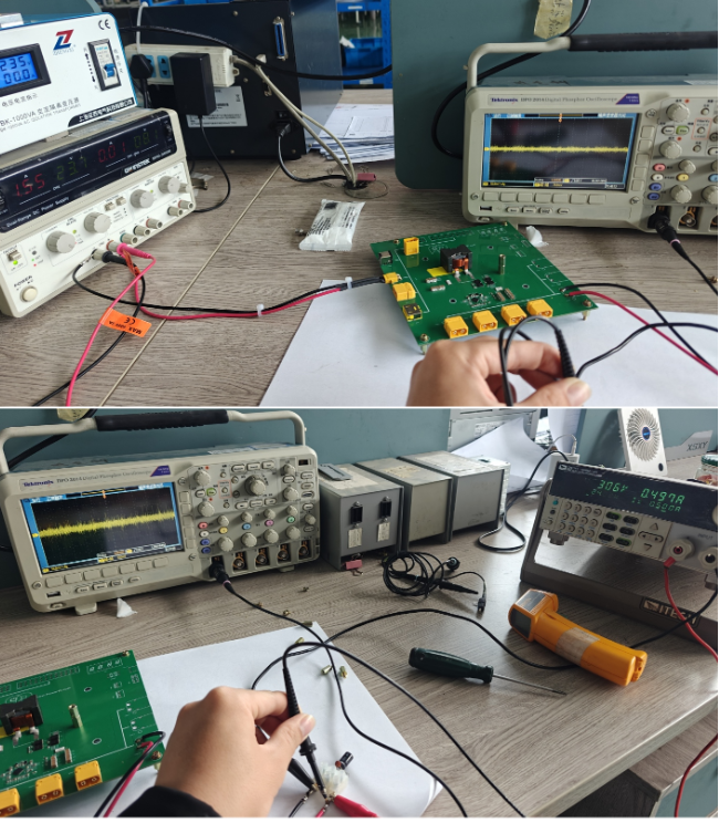
At room temperature around 17°C, with 24V input and 150W load, the board held steady for 2 hours. It’s expected that for laptop or phone chargers under 200W, no extra fan cooling is needed.
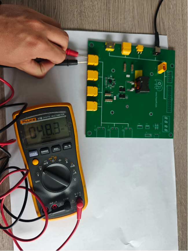
Within the input range, the no-load output is stable at 48.3V (adjustable power supply only tested 3–60V range).
Temperature under 150W load:
Room temp 17°C, 60% humidity, 48V 3A constant current mode, 2 hours.
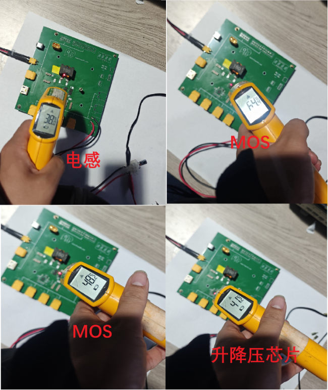
Temperature after 2 hours under 150W load:
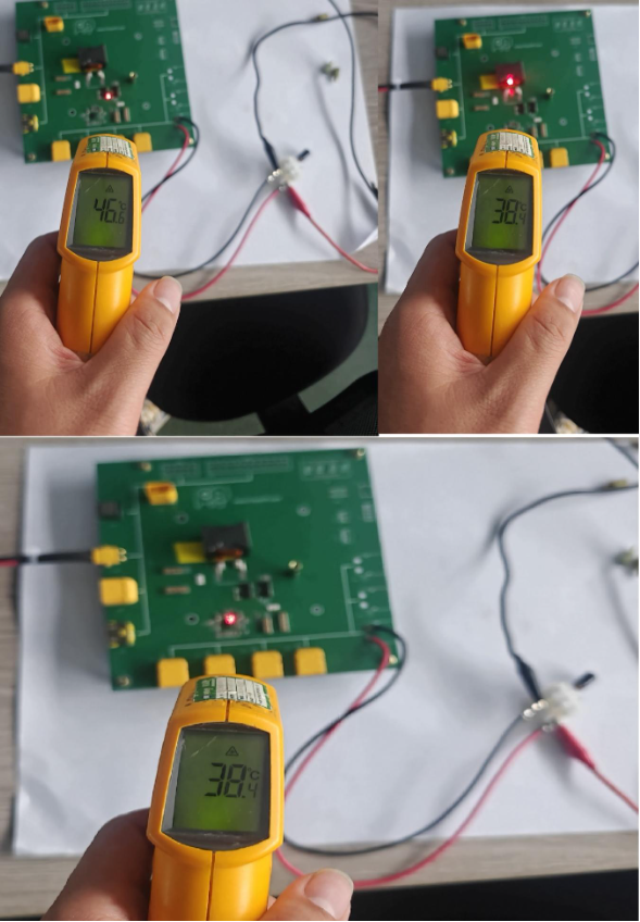
Measured a few minutes after starting 150W load.
Ripple and efficiency:
Efficiency: 30.3V*4.92A input, output on electronic load 144.3W, efficiency 96.7%
(input-output wires 0.3m, 18AWG, wires a bit thin, for reference only).
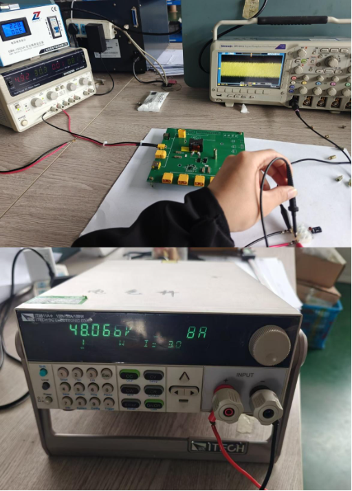
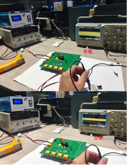
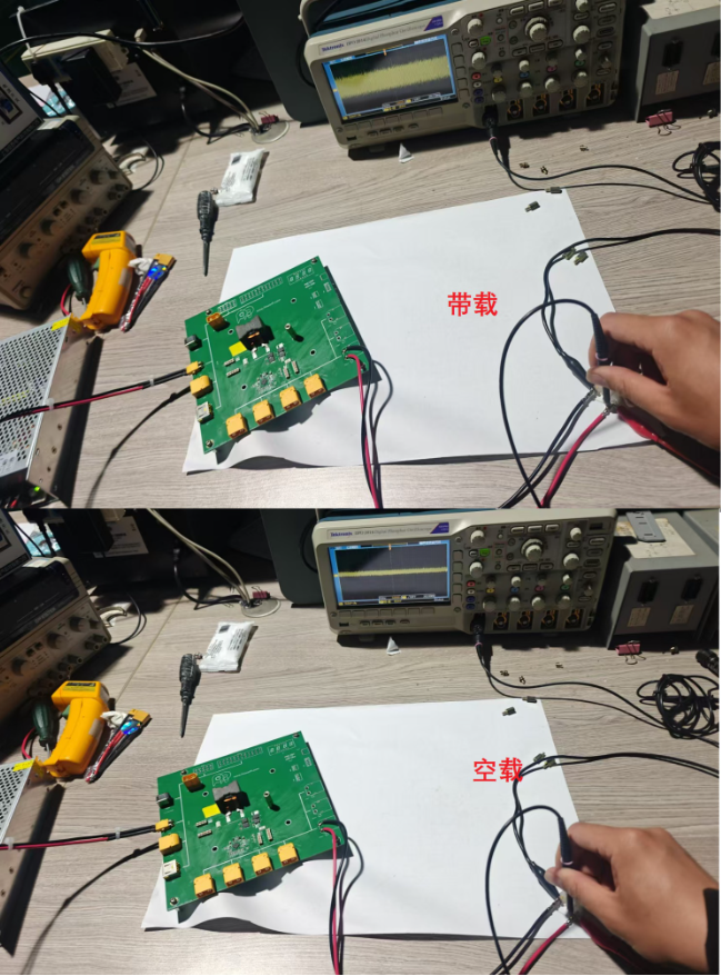
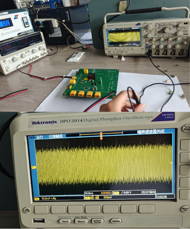
Ripple:
1. Two switching power supplies with test voltages of 24V 6.7A showed ripple of 122mV at no load and 244mV under load.
2. A 30V 5A adjustable power supply showed 88mV at no load and 264mV under load.
Using a 20MHz, 10X voltage probe, a 150W load tester measured full-load and no-load ripple.
The testing environment isn't great, so there shouldn't be significant errors. At other voltages, it was 358mV, controlled within 1% at 48V.
Application idea
Before the release of notebook 100W PD protocol USB-C chargers, most power supplies were big bricks below 20V. These notebook chargers were mostly for gaming laptops and such, at 120, 150, 180, 200W—plenty of power but voltage too low. DIY solutions were basically all step-down designs. Notebook chargers are mostly below 20V, but 100W PD fast charging usually requires power above 20V, which means a boost-buck or boost chip is needed. This PowerPi ITXPower dev board gave me a new idea: you could first step up the power supply voltage to 48V, then use various modules to step it down to the needed voltages. Efficiency will take a hit, but the upper limit is high—for example, 48V 5A could make a 240W charger.